VoIP systems and internet connectivity provide a unique opportunity for companies with multiple locations to communicate inexpensively around the world. With the proper technology, it is possible to connect two different telecommunication systems with VoIP; enabling free communication between the two systems. To do this, both systems must be compatible with VoIP. Luckily for owners of legacy communication systems, beroNet VoIP Gateways are designed specifically to make this possible.
In this tutorial, you will learn how to connect two different ISDN communication systems using beroNet VoIP Gateway technology.
Getting Started:
Choice of the gateway:
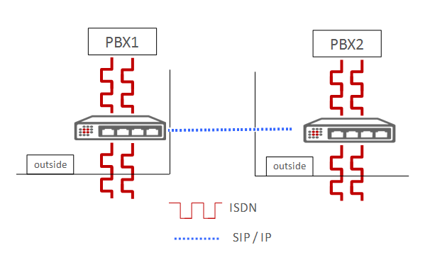
Before purchasing a beroNet VoIP Gateway, determine what technology your current telecommunication system is using. In this example, both locations use telecommunication systems with two BRI ports. Therefore, each PBX needs a beroNet VoIP Gateway with four BRI ports; two ports to connect to the PBX, and two additional ports to connect with the outside world.
Here is a graphical representation of the scenario described:
Network configuration
VoIP communication between a company’s different locations begins with creating a network link between the two locations. Two techniques can be used, though we highly recommend using the second technique as it is much more secure.
- Connecting both gateways by opening a port in each firewall
Here, most of the work will happen in the configuration of the router at each site. Ports for VoIP and RTP range will need to be opened in order to connect both gateways. When doing this, keep in mind that opening ports is like building a stone bridge over a moat. It may make traffic easier and more reliable, but it will also create a direct route for an invading army (or hacker) to attack. If you choose to use this option, ensure you have set secure passwords to protect your system. - Connecting both gateways through a VPN (preferred method)
Using a VPN is like building a labyrinth around your castle. Much more secure than opening a port. Companies with multiple locations often build a VPN between their locations for the purpose of file sharing. If such a VPN exists, it may be possible to use it for VoIP. If not, you would need to set one up. Once the VPN has been set up, both gateways can be connected with each other by creating building a SIP trunk between them. Keep in mind – if VPN connectivity is slow – voice communication will be choppy over a VPN.
Once your network configuration is ready, it is time to configure the beroNet VoIP Gateways.
Configuration of the VoIP Gateways
The configuration of both VoIP Gateways is the same. First we need to configure the ISDN ports and SIP setting. Following this you can link the technologies with the dialplan. The dialplan allows you to determine how communication over the device will be routed. Use our guide on Understanding the beroNet Dialplan to learn more about how this works.
Hardware configuration of the gateway
First, set the hardware configuration of the ISDN ports. In this scenario, two of those ports need to be set as TE (terminal Endpoint) to connect the two external ISDN lines with the gateway. The remaining two ports should be set as NT (network terminator) to connect the PBX with the gateway. To do this, navigate to “hardware” and change the “Type” of two ports to “NT”. The two others can be left as TE. Save the configuration. A red activate will appear. When you click this the gateway will restart. You can choose to click this now, or wait to activate the device until after you’ve configured all of the settings.

Next, navigate to “ISDN BRI” under “PSTN+”. Add two groups of ports. One for the NT ports and one for the TE ports. Do not forget to enter the country and city code. Save the settings.

Your ISDN configuration should look like this at the end:

The same configuration should be done in both gateways.
SIP configuration of the gateways
This part varies slightly based on whether you are using a VPN or if you opened a port in your firewall. Either way, navigate to “SIP” under “SIP+” and add a SIP account. Give it a name. The server address is the IP address of the gateway installed on the other site if you chose the VPN option. If you chose the port forwarding option, enter the external IP address of the other site and the port chosen for SIP connections.

It is not necessary to “register” both gateways with each other. Selecting this allows you to better monitor the connection, both in the GUI and the beroNet Cloud.
Once the SIP and ISDN configuration is done and you’ve activated your device, your “State” page under “Management+” should look like this:

Dialplan configuration
In this scenario, we want to send some calls via SIP when employees of one site want to call the employees of the other site, and the rest of the calls via ISDN. It is also possible to develop a more complex Dialplan for the purpose of least cost routing. This could be particularly valuable if both company locations are in different countries.

Using the dialplan we will distinguish which calls should go out via SIP and when they should go out via ISDN. In this scenario we will use a prefix dialed through PBX1 to determine which calls are sent over the SIP connection to the other company location.
CAREFUL:
- Usually PBXs already use a prefix to call out. This should not be forgotten by the employees. They would have to combine both prefixes to call the PBX2
- The prefix used on the gateway should not create a conflict with any existing numbers such as emergency numbers.
Ex: we can use the prefix 111. As this rule is more precise, it needs to be placed above the ISDN to ISDN rule.

In this case, all calls starting by “111” will be sent to the other gateway. In the other gateway, the rule “SIP to ISDN” (the second one in the above screenshot) will then forward the call to the PBX2. As explained in the dialplan how to, the “111” used as a prefix will not be sent by the gateway so that the PBX2 will recognize the extension being called.
The same four rules need to be created in the gateway in the other site. Both sites are now connected and can communicate via SIP for free.
Least cost routing
If both sites are in different countries a least cost routing scenario will save a company in long distance calling. If PBX1 is in France and PBX2 in Germany, PBX1 has the possibility of using the ISDN lines of PBX2 when calling German numbers. Two new specific rules need to be created.
Ex:

Thanks to the first rule, employees in France using the PBX1 will be able to use the ISDN lines of PBX2 in Germany when calling German numbers. In PBX2 a rule forwarding calls coming from SIP and calling a German numbers should be sent to the ISDN lines.
The second rule enables calls coming from PBX2 and calling French numbers to use the ISDN lines of PBX1.
The dialplan of the gateway 2 would then look like this:

As we can see, both dialplans are very similar.
Here is a graphical representation of the scenario we have created: